
Drone
Assembly
Building the airframe, in the order that doesn't require taking anything apart again.
The order on this page is not one of several reasonable orders. It is the one the platform teaches, and most of it exists because doing it any other way means undoing something later.
Every picture here is a render of the same 3D model that drives the assembly workbench in the app, so what you see below and what the app shows a student are the same build, in the same order, by construction.
Before you start
The whole aircraft is held together by one screw. Eighty-two of them, all identical: M3 × 5 button heads. One driver fits the entire build, and a screw left over at the end is always a screw missing from somewhere, never a spare.
Lay everything out before you pick up the driver. Seventy-four components and eighty-two screws is enough that “I’ll find it when I need it” stops working around step 3.
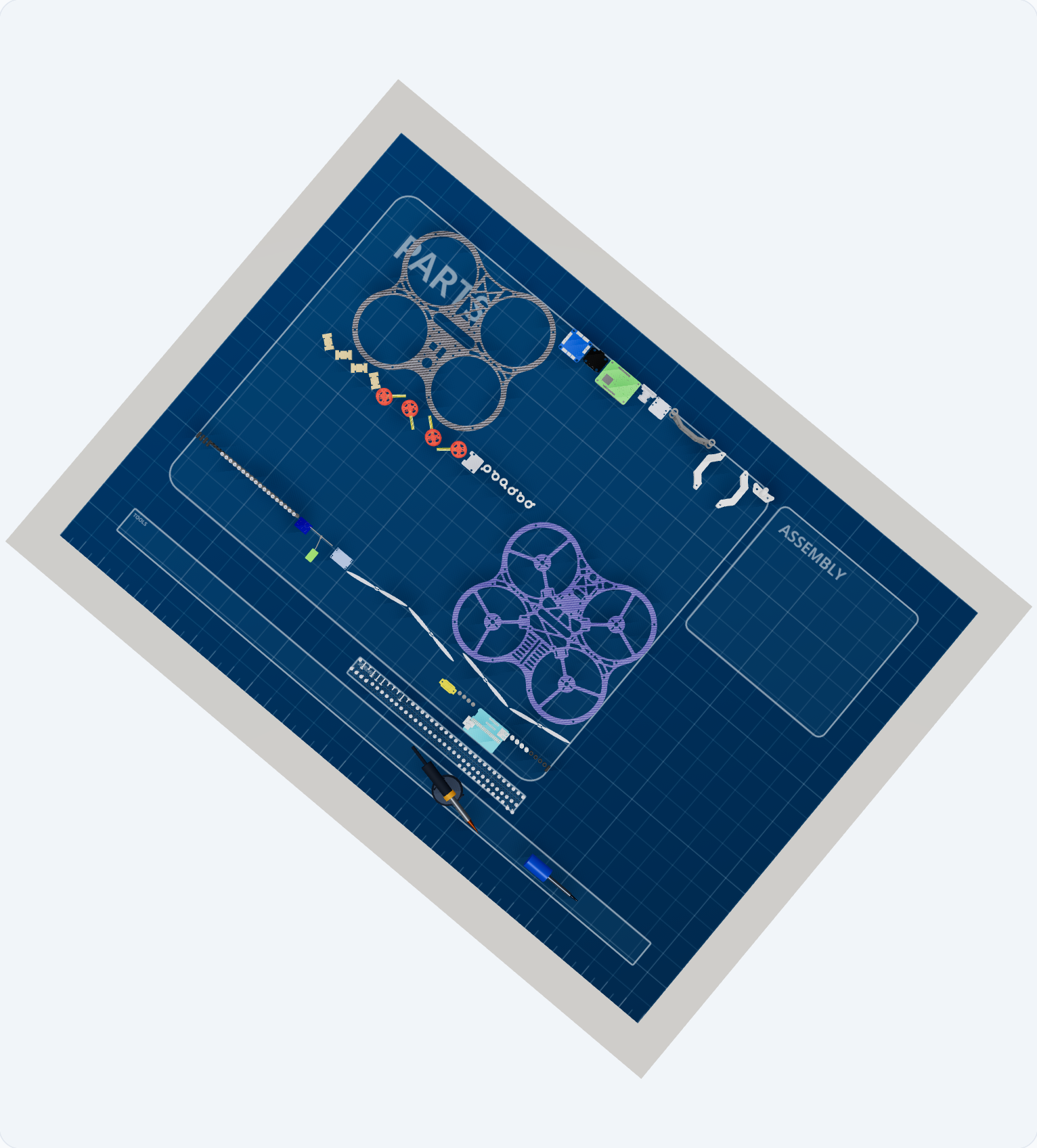
Every part, before anything is joined. The screws get their own bin for a reason — eighty-two of them mixed into the tray swamp everything else.
The build is a sandwich, and it is built bottom-first. Two carbon plates with everything of consequence between them. The bottom half is completed entirely — structure, sensors, cameras, flight controller, companion computer — and only then does the top plate come down. Everything that hangs from the top plate is fitted afterwards, from underneath.
The build
Bottom half of the frame
The bottom plate, its landing feet, the standoffs the boards and the forward camera will later sit on, the eighteen inter-frame spacers, and the front camera bracket. Eighteen screws.
Two things in this step are easy to leave until later and cannot be:
- The spacers. They stand on the bottom plate and span the whole gap to the top plate. Sixteen of their screws go in from underneath, so this is a step where the frame gets turned over, driven, and turned back — exactly as you would do it on a bench.
- The front camera bracket. It also spans the gap, and it is clamped in place when the top plate comes down. If it is not standing before that happens, it does not go in at all.
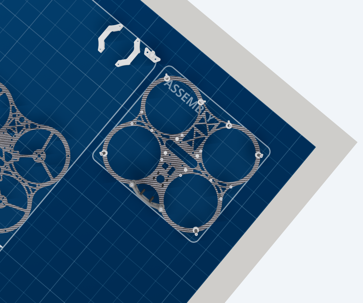
Sensors and cameras
The optical-flow and LiDAR board, its mount, and both FPV cameras — forward and downward. Eighteen screws, and this step is driven one screw at a time rather than in a batch, because the parts are small and the fixings are close together.
This comes before the computer goes in, and that is the whole point of it being its own step.
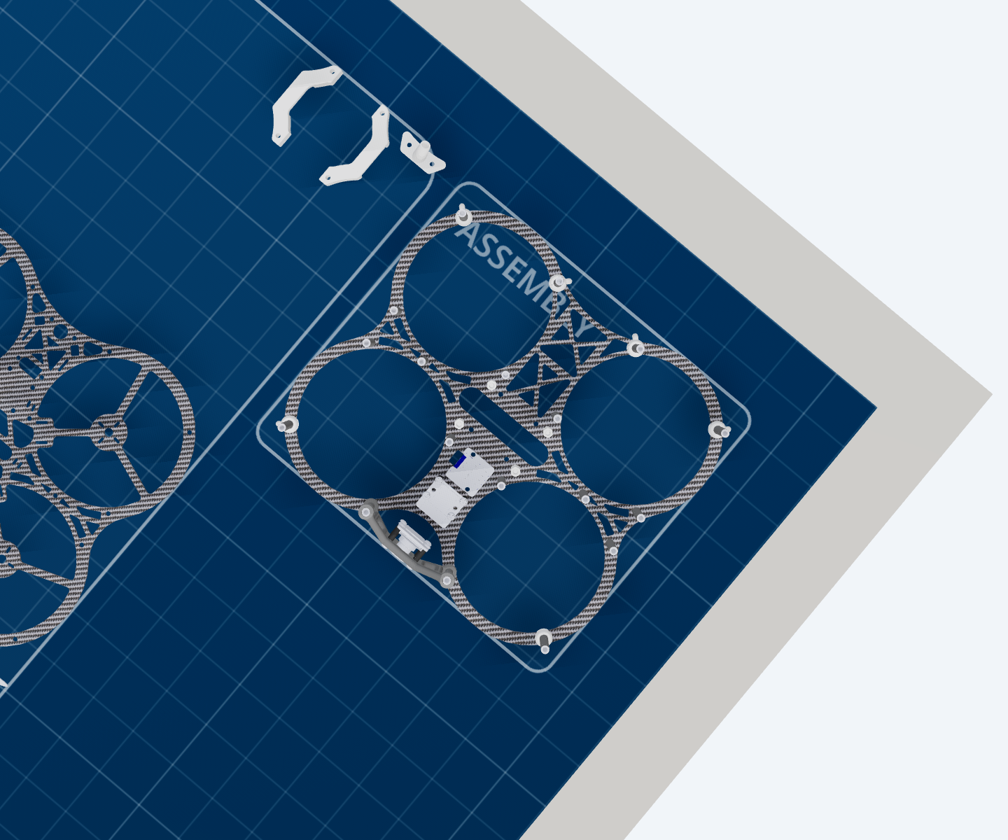
Electronics on the bottom plate
The four rubber vibration dampers, the flight controller on top of them, the companion computer on its own standoffs, and the computer’s top mount — which arrives with the USB-C board already soldered to it, so the two go on as one piece. Sixteen screws.
The flight controller sits on dampers rather than on the plate for the obvious reason: it is the thing measuring how the aircraft moves, and four motors are about to be bolted to the same structure.
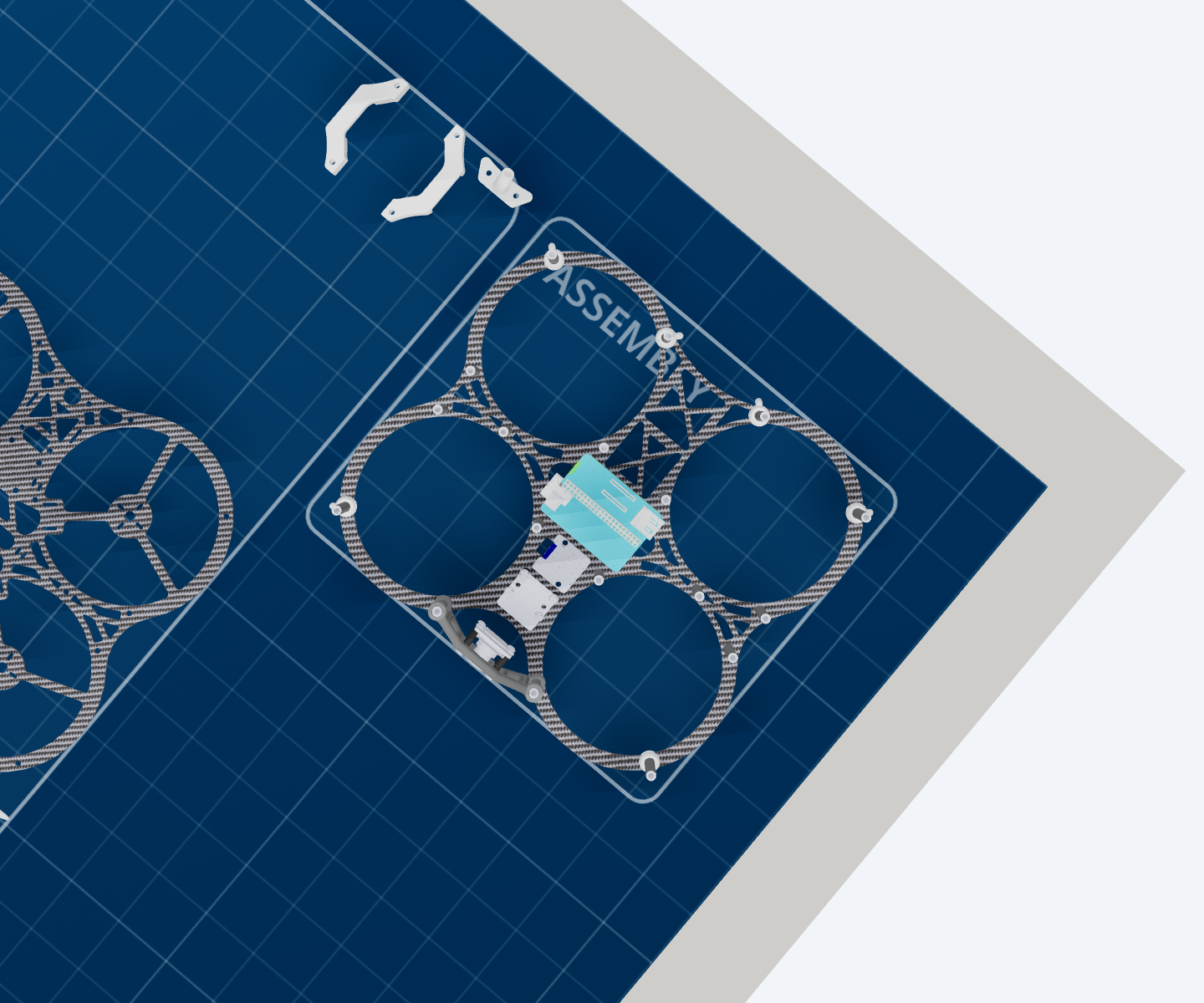
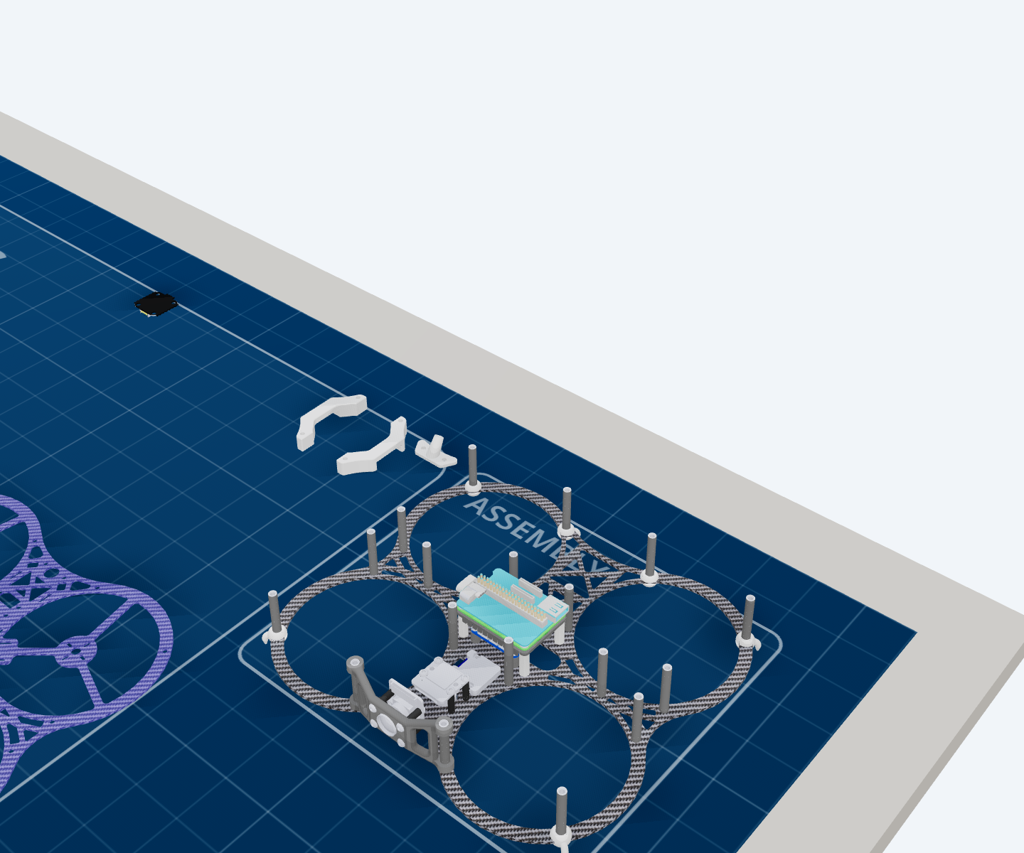
The same step from bench level. This is the view that explains the order: every one of those boards is reachable now, and none of them will be in two steps’ time.
Top carbon plate
One part, no screws, and the most consequential step in the build: the top plate comes down onto the spacers and the bottom half is closed.
It is a step of its own in both the Basic and the Full build, and that is deliberate — the boundary between the halves is what stops the build sealing itself shut with something still to do inside.
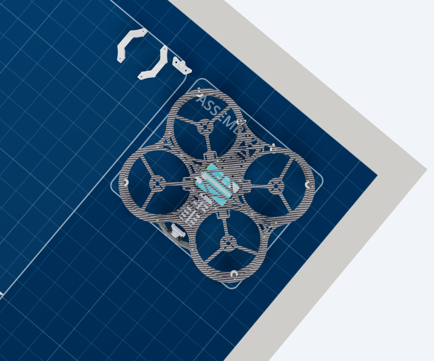
Electronics under the top plate
The four standoffs that hang down from the top plate, the 4-in-1 ESC on them, the battery lead and the four motor connectors, the computer’s power supply and the receiver. Eight screws.
The standoffs go on after the plate, not before. Fitted before it, they are four poles standing in mid-air with nothing to hang from — which is exactly how it looks, and exactly how it was got wrong once.
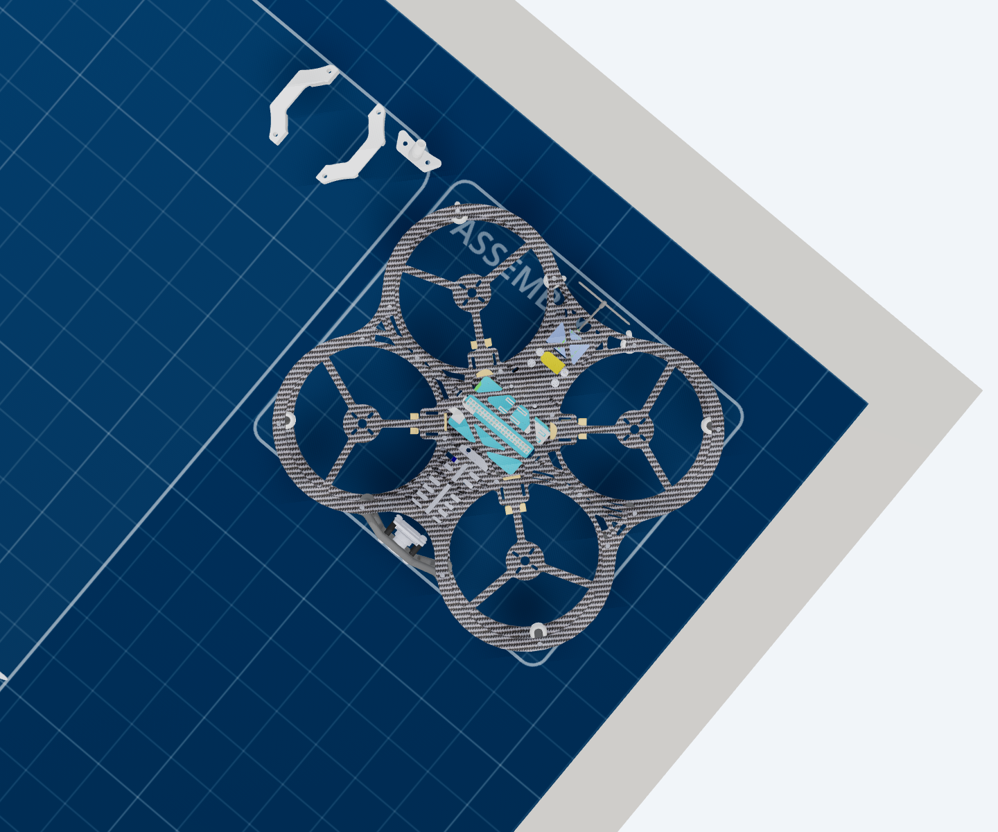
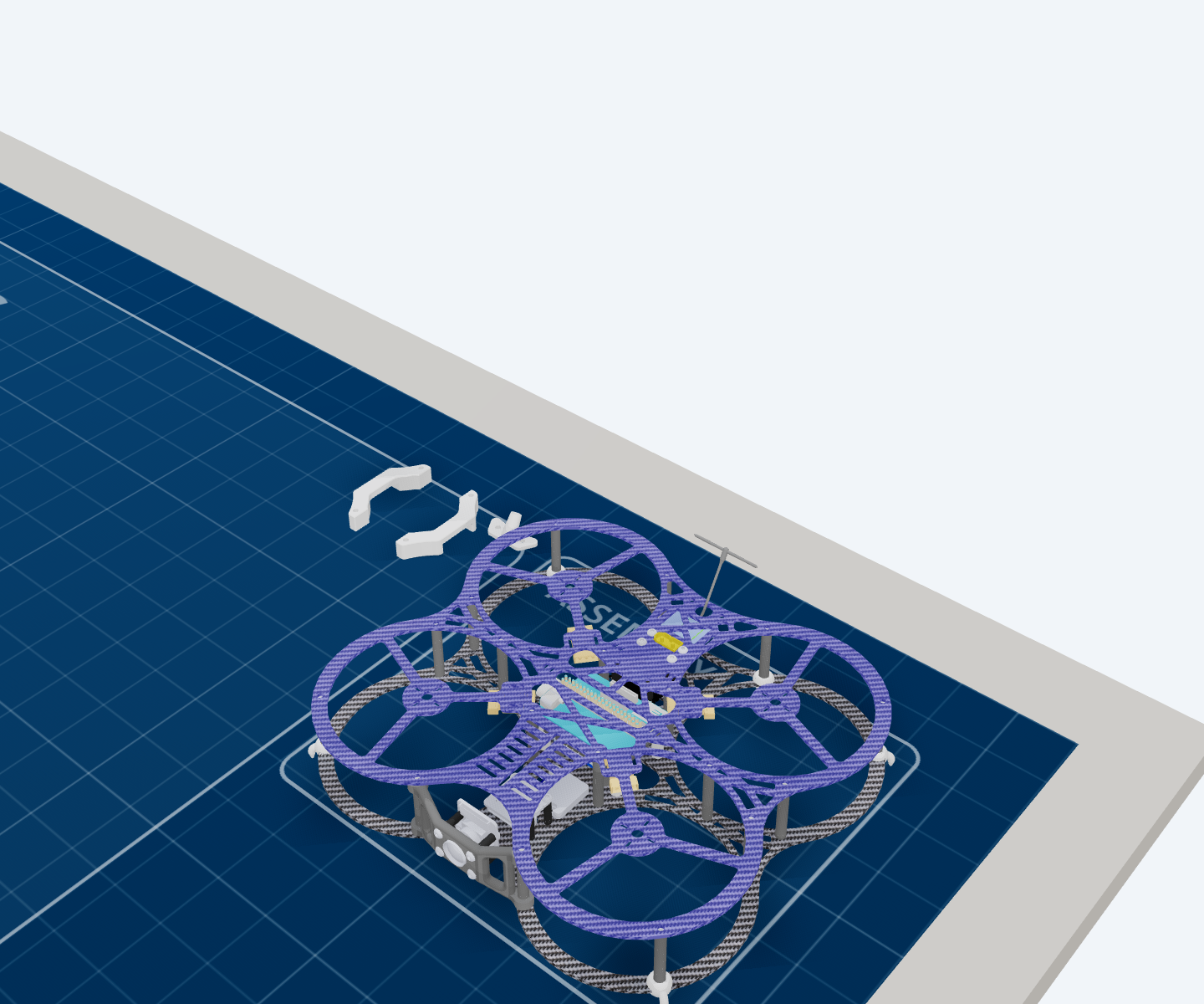
The sandwich, closed. The spacers between the plates are the aircraft’s structure — the two carbon plates do very little on their own.
Brushless motors
Four motors, and no screws in this step — none of the eighty-two belong to it.
They go on after the top plate because they pass through the housing. The geometry alone would allow them much earlier; the order here is somebody’s workshop knowledge rather than something the model worked out, and it is pinned in place by a test so nobody optimises it away.
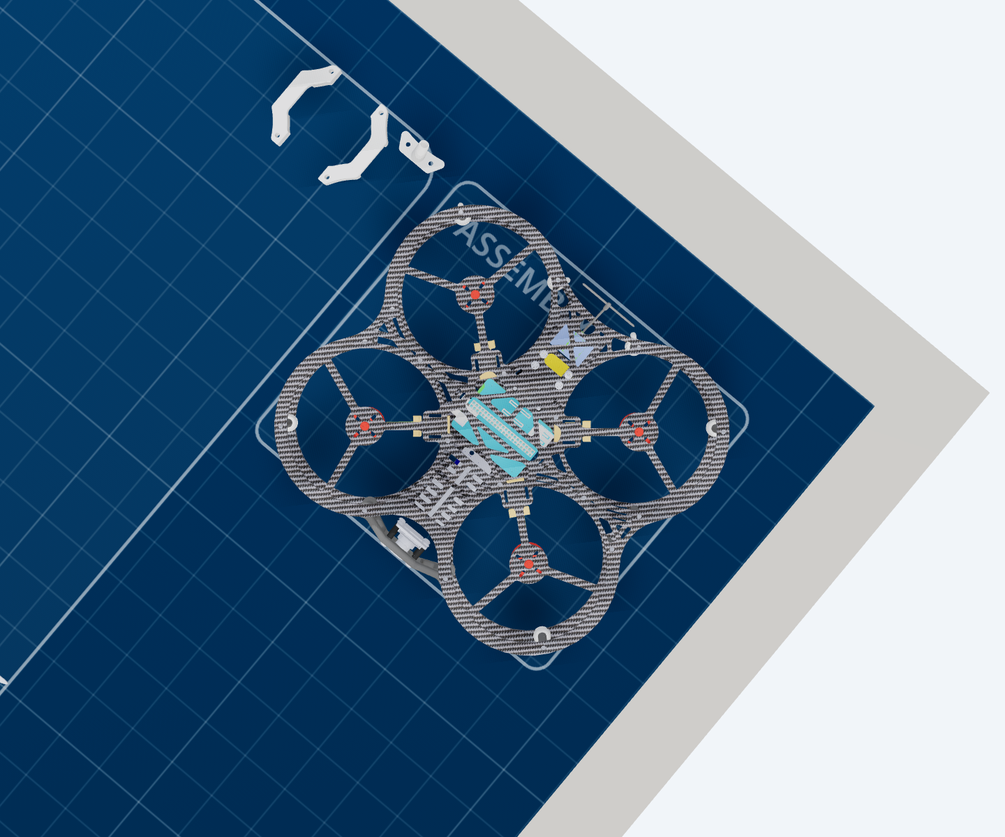
Propellers
Four propellers. On the bench, this is the last thing you fit.
In the room, it is the last thing you fit — and you fit it somewhere else. See Safety, which is not a formality on this particular step.
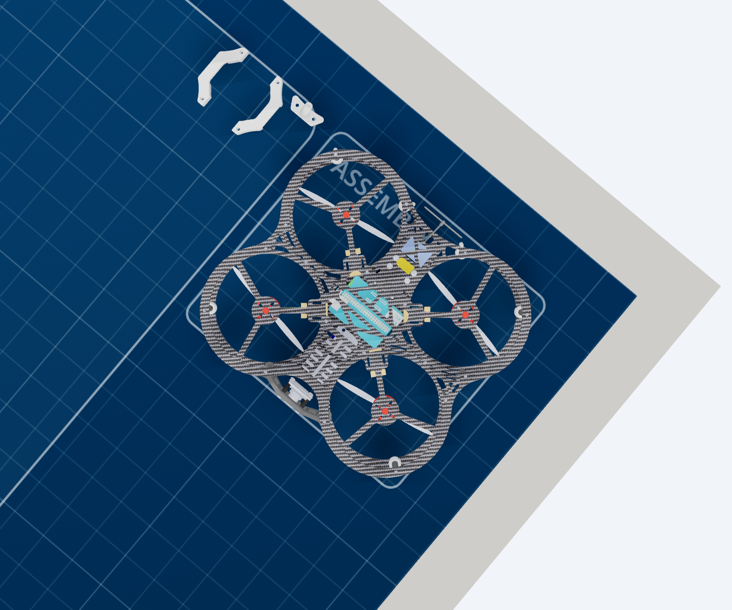
Antenna holder and battery mount
The antenna holder and the battery mount. Four screws.
Small parts, fitted last, and both of them things that get knocked in a classroom — worth a look every time the aircraft comes out of its case.
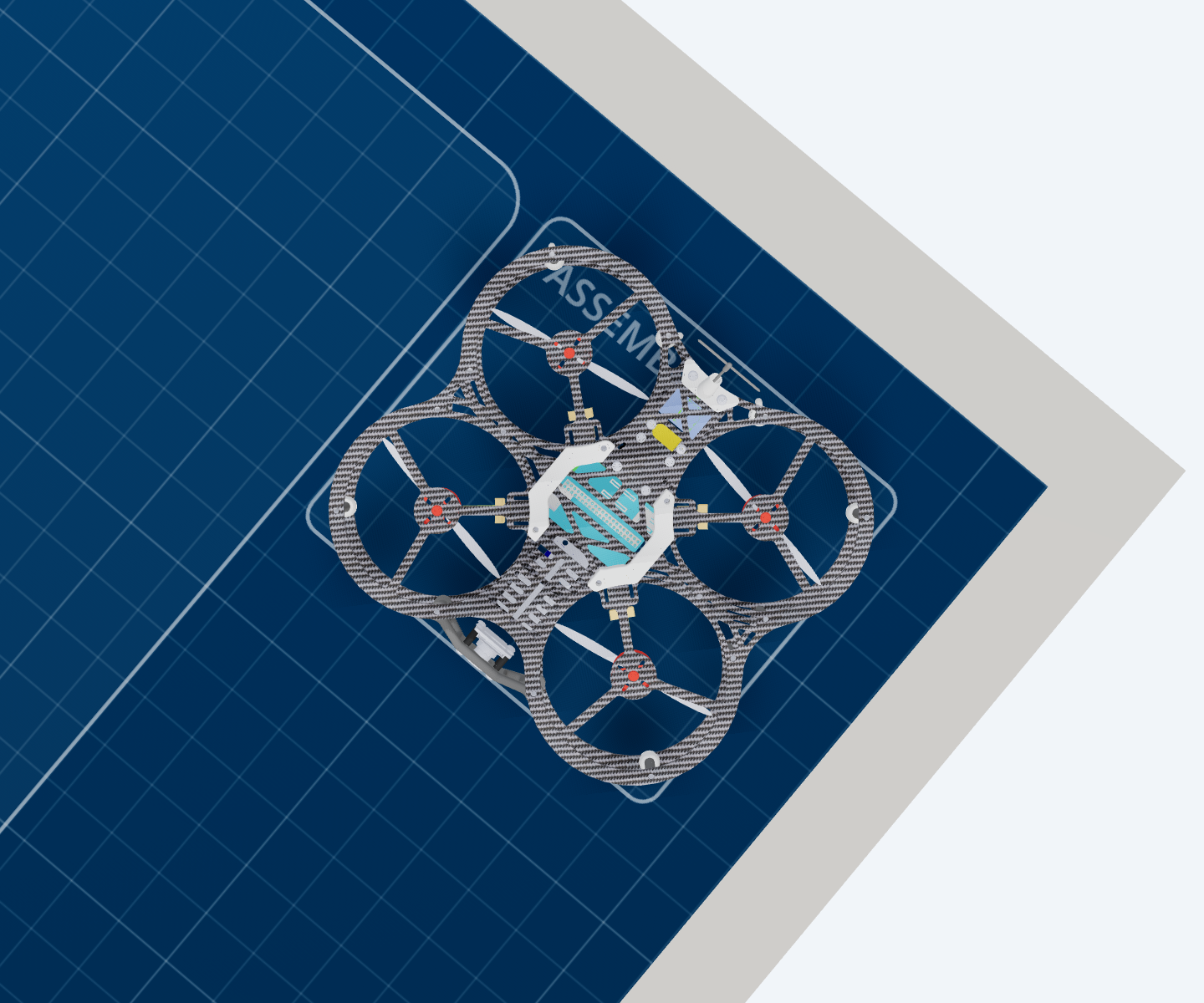
Secure the top plate to the bottom
Turn the whole thing over and drive the eighteen screws that pass through the top plate and into the spacers below it.
This step installs nothing. Both halves are already built; what it does is turn two finished halves into one aircraft. It is last because until now the top plate has only been resting on the spacers, and everything that had to reach inside still could.
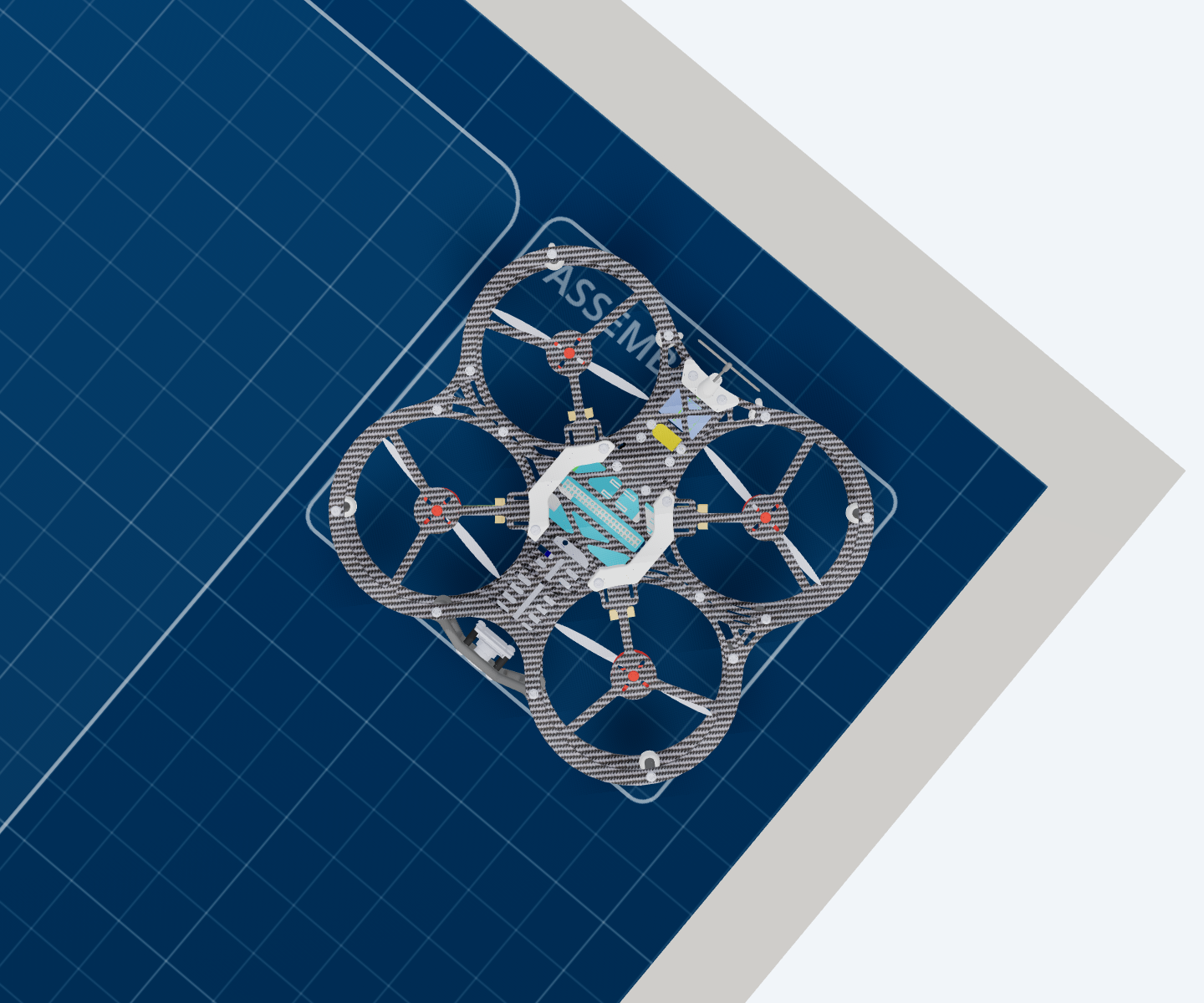
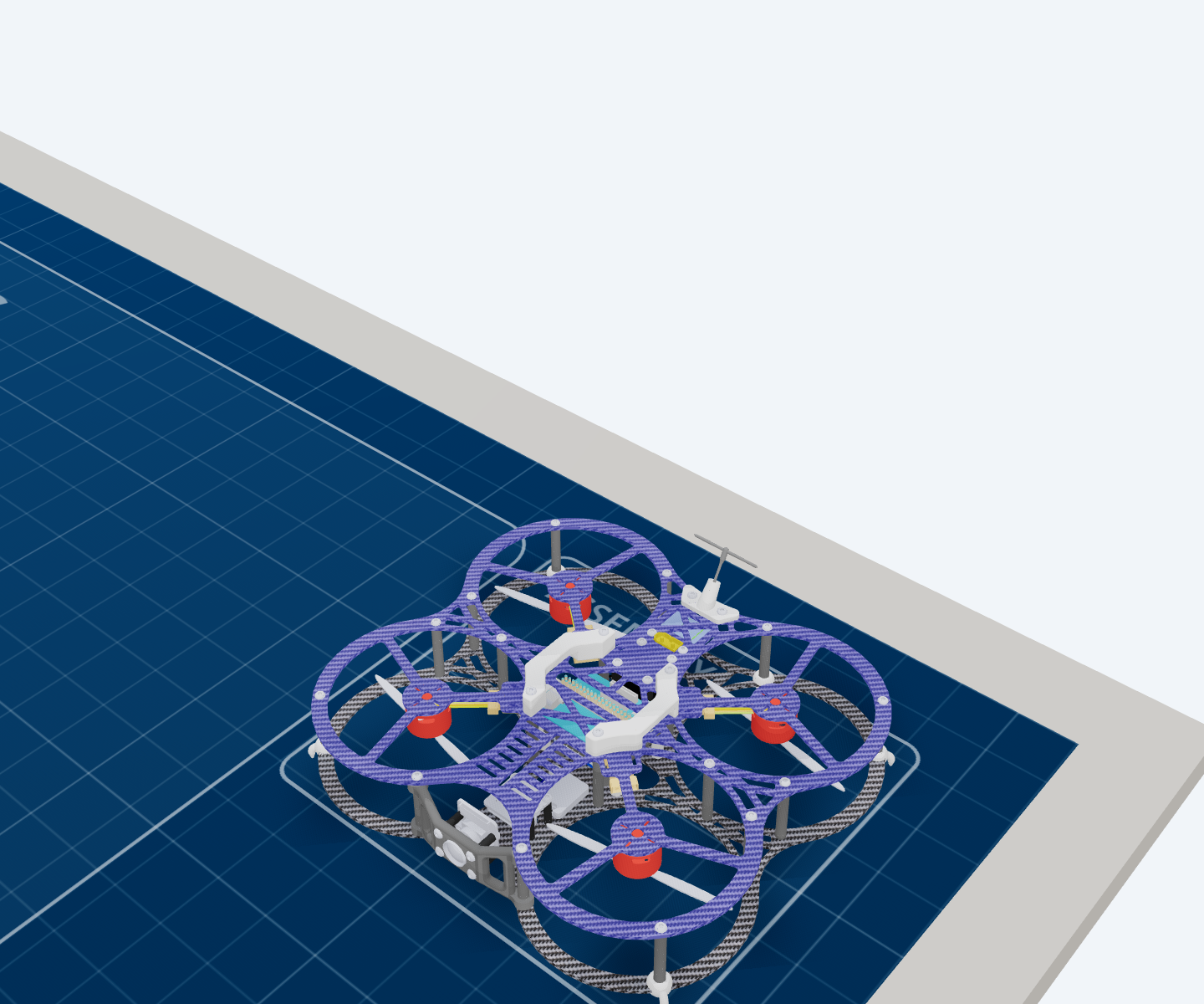
Finished, and the reason for the last step is visible from here: those eighteen screws are the only thing tying the two plates together.
Build it on screen first
The app has the same build as a workbench you can drive: Robotics → Drone Assembly Workbench.
The first two steps, played at double speed. The list on the left is the same nine steps as this page, and the counter beside it is parts placed out of 155.
- Watch replays the build a part at a time. Next advances one action, not one step — a single step can be eighteen screws — so to jump about, click a step in the list rather than pressing Next repeatedly.
- Practice hands you the parts and asks you to place them, with three difficulty settings.
- Basic is the nine steps on this page. Full build is the same seventy-four components resolved into eighteen finer steps, which is the one to use if you want the order at the level of individual boards.
- Clicking any part opens its details, which is the quickest way to answer “which of these is that?” while holding the real one.
Next
→ Safety — read before the propellers go on, not after.